

Inside a charger, the voltage goes up before it comes down. On a 230 V supply, the DC in its bulk capacitor sits at roughly 325 V, because the rectifier charges it to the peak of the AC wave.
Anatomy: what's inside
EMI filter
Stops the charger’s fast switching from sending electrical noise back into your home wiring.
Bridge rectifier
A diode bridge that turns the alternating current from the wall into direct current.
Bulk capacitor
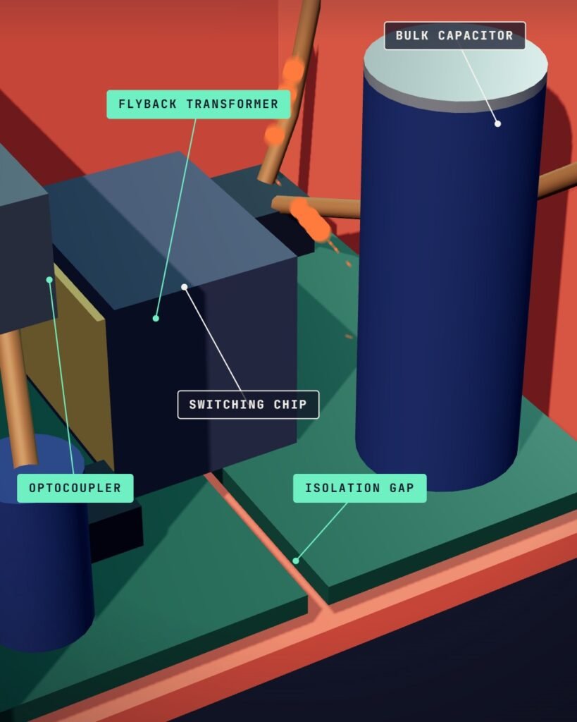
Stores the rectified high-voltage DC and keeps it steady. It can stay charged after unplugging.
Component: CapacitorSwitching transistor
A silicon or GaN transistor that turns the high-voltage DC on and off many thousands of times a second.
Controller chip
Decides how long the transistor stays on in each cycle, to hold the output voltage steady.
Flyback transformer
Stores energy while the switch is on and releases it to the output while it is off. It lowers the voltage and isolates you from the mains.
Component: TransformerOutput rectifier and capacitor
Let current flow one way only and smooth the pulses into steady low-voltage DC.
Component: CapacitorOptocoupler
A tiny LED and light sensor in one package that sends the output voltage reading back to the controller without breaking the isolation barrier.
Component: SensorUSB PD controller
Talks to your phone over the USB-C cable to agree on a voltage, such as 5, 9, 15 or 20 volts.
A power station in your pocket
The socket in your wall supplies alternating current at somewhere between about 100 and 240 volts, depending on the country. Your phone’s battery wants a few volts of direct current. A modern USB-C charger has to bridge that gap, keep you safely separated from the mains, and do it in a box small enough to carry in a pocket.
It does this with a switch-mode power supply, and a common design for phone chargers is the flyback converter. Texas Instruments calls the flyback the lowest-cost isolated power converter, used in everything from televisions to phone chargers.
This article follows the power through a real design: TI’s 65 W GaN USB-C charger reference design, which accepts anything from 90 to 265 volts AC and delivers 5, 9, 15 or 20 volts to a phone or laptop. Its five stages, in order:
- Rectifier. Mains AC becomes high-voltage DC.
- Switch. A transistor chops it into fast pulses.
- Transformer. The energy crosses to a separate low-voltage winding.
- Output stage. The pulses are smoothed into steady DC.
- Feedback. The charger checks its output and agrees on a voltage with your phone.
Step 1: turn AC into high-voltage DC
The first thing a charger does is not lower the voltage. Power comes in through an EMI filter, which keeps the charger’s fast switching from sending electrical noise back into your home wiring, and then into a rectifier stage. In TI’s words, the diode bridge rectifies the AC line voltage and stores energy in the bulk capacitor, which maintains a relatively constant positive voltage.
That voltage is high. A rectifier charges the capacitor to the peak of the AC wave, which is about 1.4 times the voltage printed on the socket, so on a 230 V supply the bulk capacitor sits at roughly 325 volts. This is usually the biggest capacitor in a charger, and the main reason you should never open one: it can stay charged after the plug comes out.
Step 2: chop it up, many thousands of times a second
Next, a transistor switches the high-voltage DC on and off very fast. A 60 W flyback example from TI, a DC-to-DC design, switches at 250 kHz, 250,000 times a second. The 65 W charger design varies its frequency between 76 kHz and 163 kHz as the load changes.
Each switching cycle has two halves. When the transistor turns on, the input voltage is applied across the transformer’s primary winding and current ramps up, storing energy in the transformer. An output rectifier blocks any current from reaching the output during this time. When the transistor turns off, the winding voltages reverse, current flows out of the secondary winding, and the rectifier conducts, delivering current to the load and recharging the output capacitors.
The controller sets how long the switch stays on in each cycle. As Monolithic Power Systems explains, this duty cycle, together with the transformer’s turns ratio, determines the output voltage.
Why the transformer can be so small
MPS describes the flyback transformer as a coupled inductor: the energy is stored in its magnetic field while the switch is on and released to the output while it is off.
Speed is what shrinks it. The power a flyback delivers is the energy stored in each cycle multiplied by the number of cycles per second, so the faster it switches, the less energy each cycle has to carry. TI’s reference design says the flyback transformer is kept to a minimum size by operating at high switching frequencies, which allow a smaller inductance, a smaller core and fewer windings.
The transformer is also the safety barrier. Its two windings are not electrically connected; energy crosses between them only as a magnetic field. MPS notes that this isolation is vital for flyback converters to meet safety standards such as UL 1577 and IEC 62368. In TI’s design, the secondary winding is made with triple-insulated wire.
Testing lab Intertek describes IEC 62368-1 as a hazard-based safety standard for audio/video, information and communication technology equipment, focused on the risks a product could present.
Step 3: smooth the output and keep checking it
On the low-voltage side, a rectifier lets current flow one way only and an output capacitor smooths the pulses into steady DC. Efficient designs, including TI’s, replace the rectifier diode with a transistor that is switched at exactly the right moments, called synchronous rectification, because it wastes less power as heat.
The output voltage must stay steady whether the phone is drawing a lot of current or almost none, so the charger keeps measuring it. But the measurement happens on the low-voltage side, and the controller sits on the high-voltage side. In secondary-side regulation, the output is sensed directly and the signal is sent back through an optocoupler, a tiny LED and light sensor sealed in one package, which transmits the signal without breaking the isolation barrier. Simpler designs use primary-side regulation, reading the output through an extra transformer winding with no optocoupler.
How the charger and phone agree on a voltage
A USB-C charger with USB Power Delivery contains a small PD controller that talks to the phone over the cable before raising the voltage. TI’s design can offer 5 V, 9 V, 15 V or 20 V. Higher voltage means more power can flow through the same cable without increasing the current.
According to the USB Implementers Forum, USB PD lets low-power devices such as headsets negotiate for only the power they require. The standard was limited to 100 W at 20 V and 5 A until revision 3.1 added fixed 28 V, 36 V and 48 V levels for up to 140 W, 180 W and 240 W.
Electrical Safety First calls this a digital handshake: USB chargers start at 5 V and stay there if the communication fails, so a device that can’t take more isn’t exposed to it.
GaN: why chargers got smaller
For decades the switching transistor was made of silicon. Many newer chargers use gallium nitride (GaN) transistors, which can switch fast with low losses. In TI’s reference design, the GaN device’s high-frequency capability is what enables its high power density.
The result is 25.29 watts per cubic inch and a measured efficiency of 92.83 to 94.32 percent at full load, depending on the input voltage. With nothing connected, the same design draws about 30 milliwatts at 115 V AC.
TI’s gallium nitride page makes the general case: lower switching losses let its GaN devices run above 500 kHz, with magnetics up to 60 percent smaller. Those are a chipmaker’s best-case figures.
Why a charger gets warm
No converter is perfect. At about 94 percent efficiency, which TI’s reference design reaches at 230 V, a charger delivering 65 W to a laptop draws about 69 W from the wall, and the missing 4 W or so becomes heat inside the case. That is why a charger feels warm while it is working hard, and why it cools down once the battery is nearly full and the power drops.
Since 2007 the U.S. Department of Energy has required efficiency standards for consumer external power supplies, though in 2025 it proposed rescinding its current rules.
What fake chargers leave out
When Electrical Safety First tested 116 counterfeit and look-alike 20 W Apple adapters from the UK and EU, 107 of them (92 percent) failed a critical insulation safety test, meaning mains voltage could reach the part you touch. Of the 56 UK samples, 71 percent failed a plug-pin strength test. Of 22 that were opened up, 68 percent had metal weights inside to make them feel like the real thing.
Everything that keeps you safe in a charger is invisible from the outside: the insulation in the transformer, the spacing between the high- and low-voltage sides, the strength of the plug pins. Those are the things the fakes in that test often skipped.
How to avoid an unsafe charger
- Buy from a reputable retailer or the device maker. Electrical Safety First warns that chargers from third-party online sellers may not have passed the necessary safety checks.
- Be wary of listings that work hard to insist a product is genuine. Electrical Safety First flags this in its warning about counterfeiters’ tactics.
- Check the pins and markings. For fake Apple adapters, the same warning says genuine pins have a matte, uniform finish, and genuine logos and text are clean and well defined.
- Unplug at once if you notice odd smells, sparking, smoke, swelling, cracks or damage.
- Watch for burn marks, buzzing or crackling, or a charger too hot to touch, and stop using it if you find them.
- Charge while you’re around. Electrical Safety First advises against charging overnight or while you’re out.
- Never open or try to repair a faulty charger.
How it works, step by step
Rectify
A diode bridge turns the AC from the wall into DC and charges the bulk capacitor to a steady, high voltage.
Switch
A transistor connects that voltage to the transformer’s primary winding, storing energy in its magnetic field.
Transfer
When the transistor turns off, the stored energy flows out of the secondary winding at a much lower voltage.
Smooth
An output rectifier and capacitor turn the pulses into steady low-voltage DC for the USB port.
Regulate
The output is measured and fed back across the isolation barrier, so the controller can adjust the switching and hold the voltage steady.
Negotiate
With USB Power Delivery, the charger starts at 5 V and agrees on a higher voltage with the phone over the cable before more power flows.
Myth vs fact
A charger is just a transformer that steps the voltage down.
A modern charger first turns the mains into high-voltage DC, then switches it at tens to hundreds of kilohertz. That high frequency is what lets the transformer be so small.
A powerful charger forces too much power into a small phone.
With USB Power Delivery, devices negotiate for only the power they require. Electrical Safety First notes that chargers stay at the standard 5 V if that communication fails.
A heavier charger must be better made.
Electrical Safety First found metal weights inside 68 percent of the counterfeit chargers it opened, added to make them feel genuine.
A charger left in the wall wastes a lot of power.
A well-designed one uses very little with nothing connected. TI’s 65 W reference design draws about 30 milliwatts at 115 V AC.
Never open a mains charger. Its bulk capacitor holds a high-voltage charge, roughly 325 volts on a 230 V supply, and it can stay charged after unplugging. Electrical Safety First advises unplugging a charger at once if you notice odd smells, sparking, smoke, swelling, cracks or damage, and buying from a reputable retailer: counterfeit chargers often fail basic insulation tests.
Questions people ask
Why does my phone charger get warm?
No charger is 100 percent efficient. A good one turns around 94 percent of the power it draws into output, and the rest becomes heat in the case. It runs warmest when it is delivering the most power.
Can I charge my phone with a laptop USB-C charger?
If both support USB Power Delivery, the phone and charger negotiate the voltage over the cable, and the phone asks only for the power it requires. If the negotiation fails, the charger stays at the standard 5 V.
What is a GaN charger?
A charger whose main switching transistor is made of gallium nitride instead of silicon. GaN switches fast with low losses, so the charger can run at higher frequency with a smaller transformer, making it smaller for the same power.
Does a charger use power when nothing is plugged in?
A little. A well-designed charger draws only milliwatts with no device connected. TI’s 65 W reference design measures about 30 milliwatts at 115 V AC.
How can I tell if a charger is fake or unsafe?
It is hard to be sure from the outside. Electrical Safety First advises buying from a reputable retailer or manufacturer and being wary of listings that stress that a product is genuine. For fake Apple adapters, it says genuine plug pins have a matte, uniform finish and genuine markings are clean and well defined. Stop using any charger that smells odd, sparks, smokes, swells, cracks or buzzes.
Sources
Published by Cut It Open. Checked against every listed source before publishing.
Facts last verified 2026-10-26
Published October 26, 2026 · Updated October 25, 2026